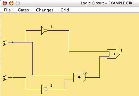
This circuit has two NOT gates, an AND gate and an OR gate.
The
output value of each gate is displayed on the wire on its right.
The
inputs to the entire circuit are set by toggle switches on the left -
each
of these can be 0 or 1. The output of the entire circuit is shown
on
the rightmost gate (in this example, the OR gate).
To change the values of the input switches, select the Changes
-> Set Switches menu item and then click on the switch to be
changed. Note how the outputs of the different gates change in
response.
1. Write down a truth table for this circuit, using A and B as
labels for the two input switches and C for the output value on the
right.
To add a new gate to a circuit, select the Gates -> And gate,
Gates -> Or gate, or Gates -> Not gate menu item.
Now click on the yellow area to place the gate. To add a
wire that connects the output post of a gate to an input post of
another gate, select Changes -> Connect gates and then click
on the two posts to be connected. To
remove a gate from the circuit, select Changes -> Delete and
then
click on the gate to be removed.
Now use these tools to create a circuit that looks like this:
2. Save this circuit as the file <yourlogin>.cir
on the desktop by selecting the File -> Save as menu item.
Drag this file to the csci105 -> Drop Box.
3. Explain briefly in English what this new circuit
accomplishes.
Once you are finished in the lab, be sure to drag the csci105 folder to the Trash - this step disconnects you from the server and prevents someone else (who may use this iMac later in the day) from accidentally accessing files in your personal folder.
To submit a handwritten assignment, leave it in the CS105 mailbox near my office (Searles 220).
Note: Even though the lab programs for this course can be
saved and submitted electronically, you should always keep a backup
copy in your
personal folder, so that if a file is lost you won't have to retype it
from
scratch.